Week 15
- CategoryWild Card week
- Sessions Date:
- Assignment:
Design and produce something with a digital fabrication process (incorporating computer-aided design and manufacturing) not covered in another assignment, documenting the requirements that your assignment meets, and including everything necessary to reproduce it.
Working with Printing Press
For this week, we were required to fabricate something using the digital fabrication process but the challenge was not to use the machines previously used. In our lab, we had Handibot and the Emboidery machine but sadly both were broken. So now we had to look elsewhere to find a mahcine which used the digital fabrication process. Luckily one of our ex-collegue who used to work in Fablab Bhutan runs a priting press company. He was kind enought to let us use the machine under his staffs guidance.
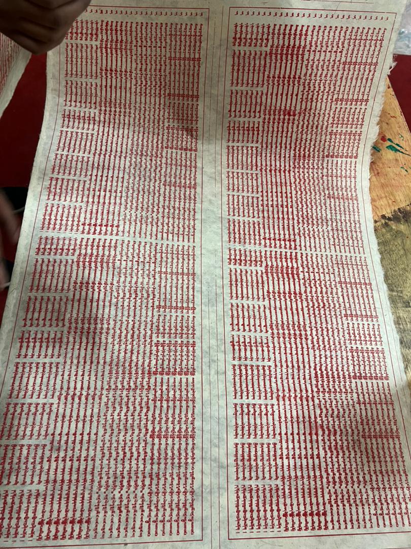
The Printing Press was used for printing religious text and mantras on papers and mainly on the traditionally made paper called Desho. One of the most key aspects while press printing is to have a pitch dark room and no exposure to light.
Designing
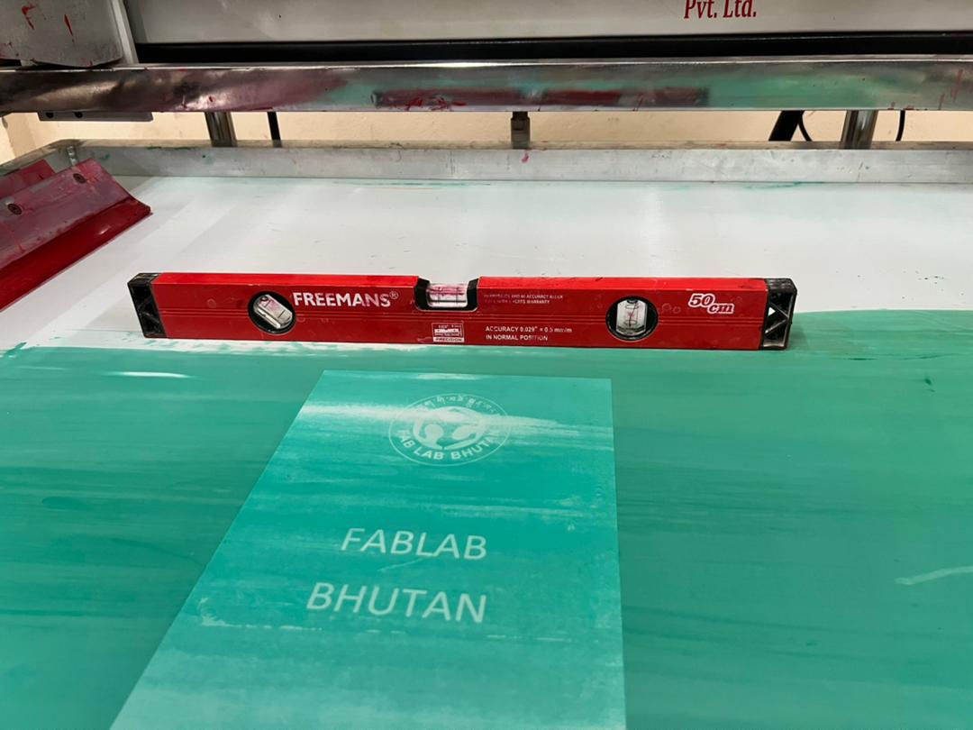
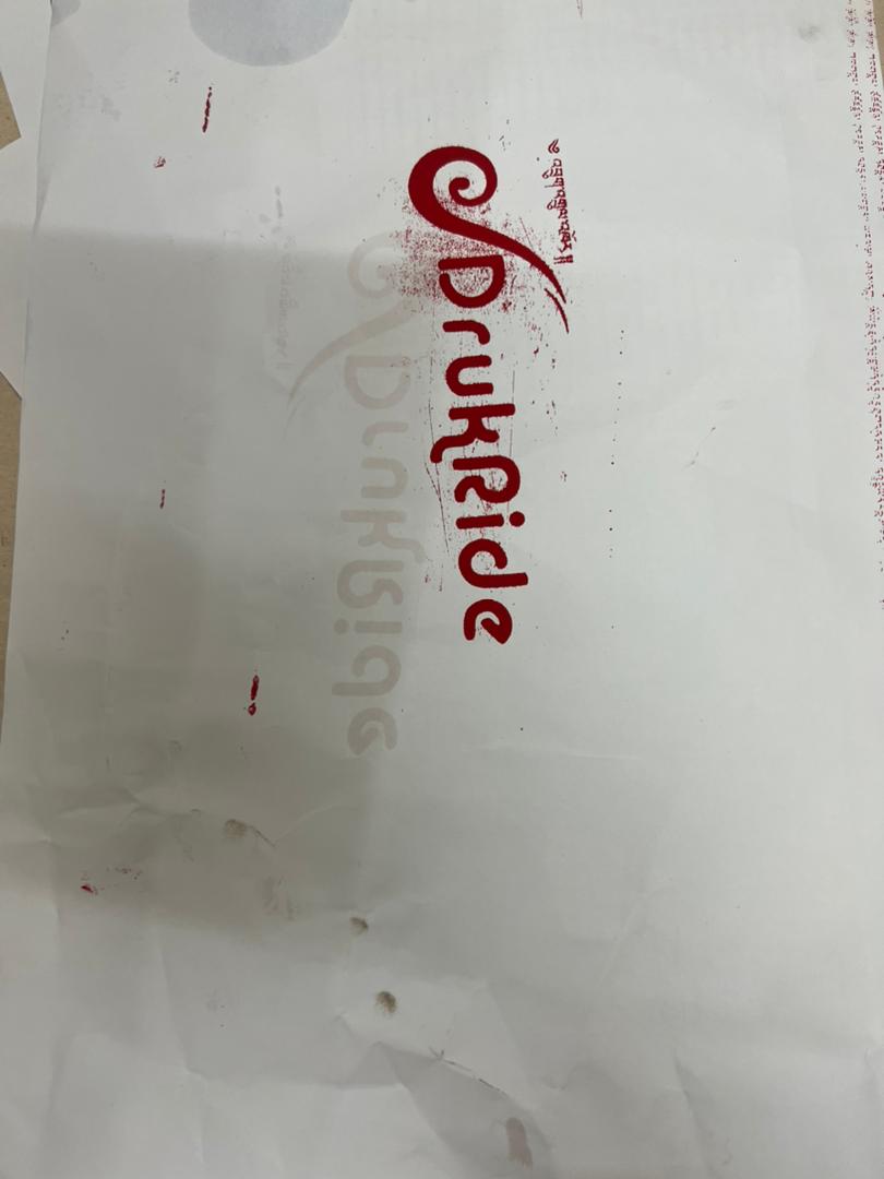
The first step to press printing is to design on any CAD software. For our assignment we made a simple Fablab Bhutan logo and took.
Adding Emulsion to the Screen.
The screen was made up of nyloon.The screen is a thin net and stretched uniformly on a wooden
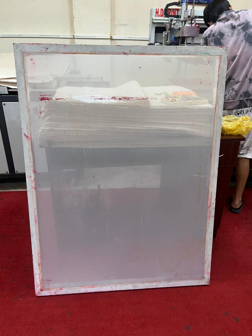
To ensure that there is no emulsion or ink left on the screen, it is first thoroughly washed with water and a brush.
The screen is then dried. We begin working in a dark room after the screen has fully dried.
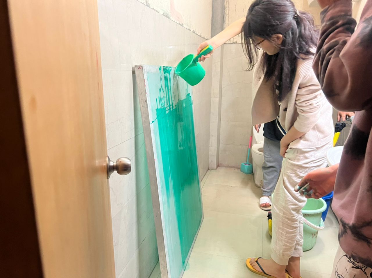
Working in a dark space is necessary to prevent UV rays from reaching the emulsion.
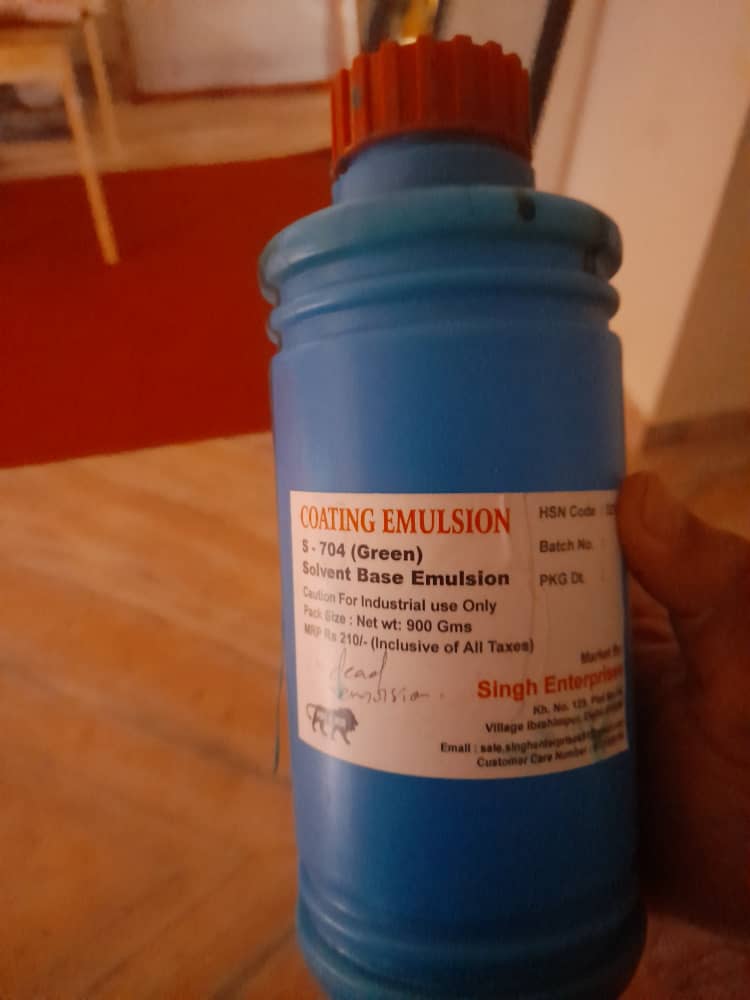
The emulsion is a liquid that becomes solid when exposed to UV light. It only has to be solidified in the absence of an image and does not set in the presence of UV light. So, in complete darkness, we gently applied the emulsion and distributed it evenly on both sides of the screen.
We use a wooden/rubber wiper to evenly apply the emulsion after applying it on both surfaces. We blowdry the screen uniformly after emulsion has been applied.
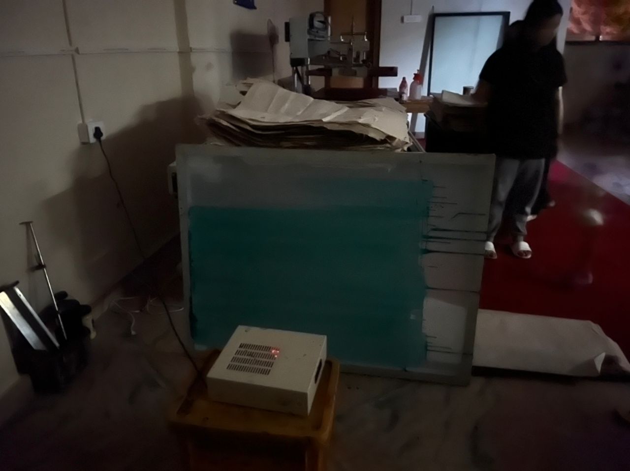
Light Exposure of the Screen
We proceed to expose the screen to UV light with the necessary design on the bottom of it once it has adequately dried and is not being subjected to any external light, especially UV light. The planned image should be dark where UV exposure won't be an issue, while UV-exposed areas will be set. This is done to remove the emulsion from the area and let the ink run through. While ink can travel through areas where there is no emulsion.
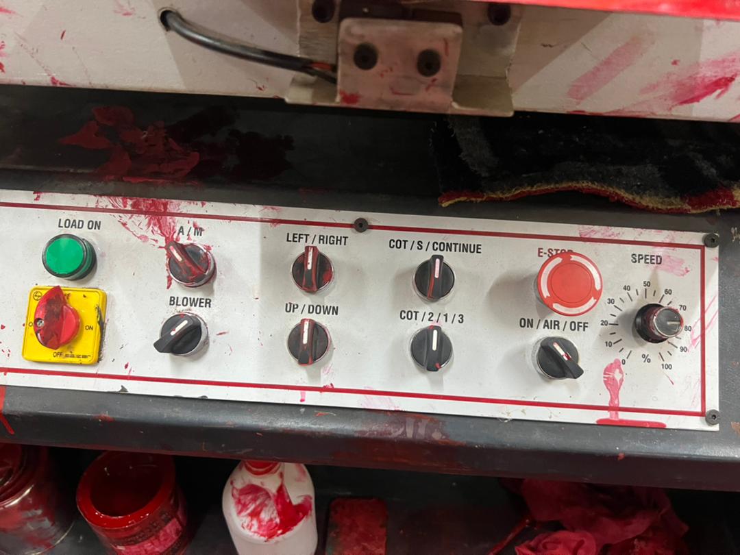
After the procedure is finished, we proceed to wash the screen before printing. The screen must be secured to the device before printing can begin. It is a semi-automatic flat screen printing device made by [SK Ensure Machinery].
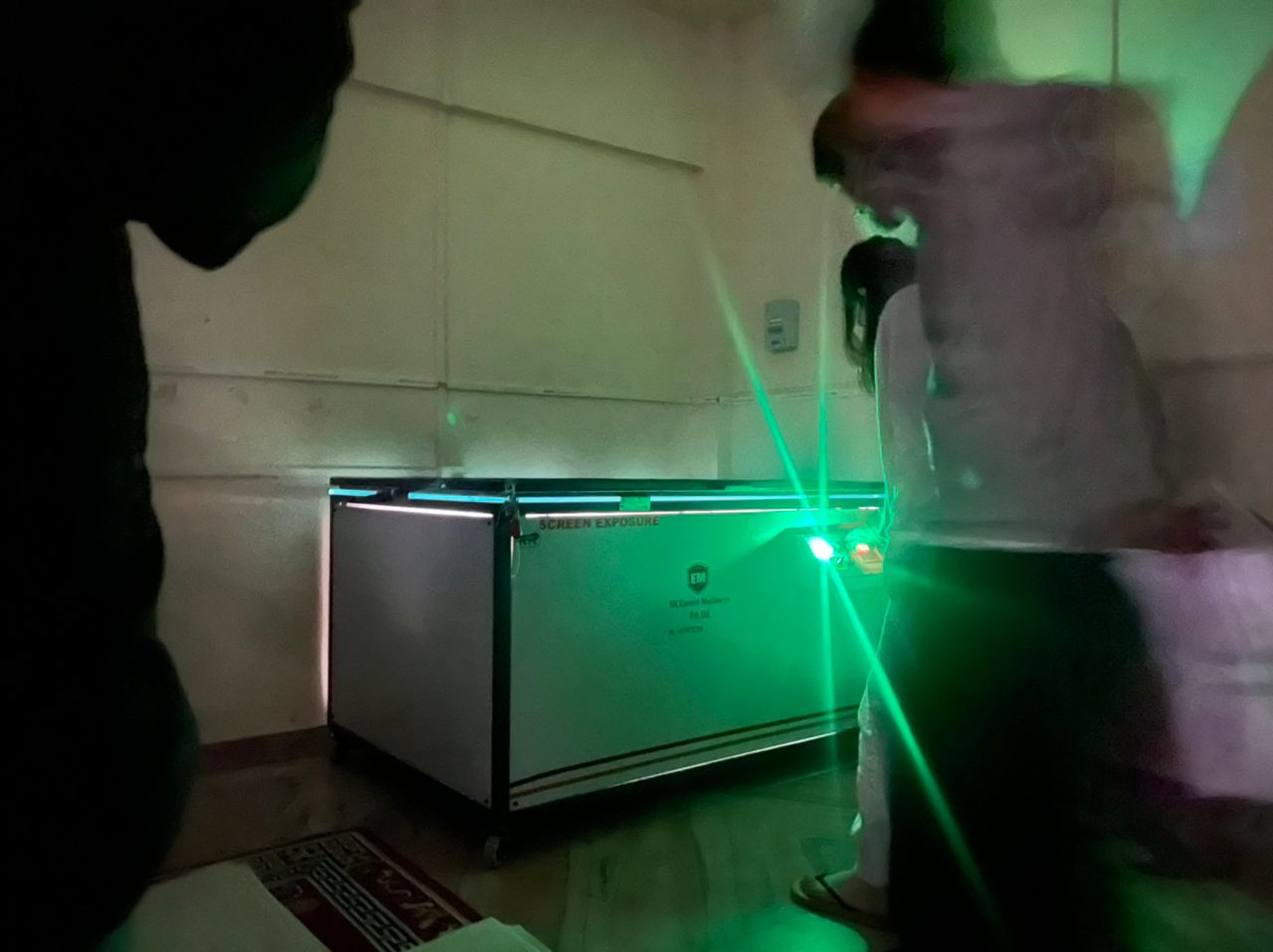
We close the lid and exposed the screen for a maximum of 2 minutes with the design print and screen attached to the UV exposure equipment.
Ink Printing process
The screen is mounted on the machine's top and securely hinged with a screw holder. The ink is applied on the screen after it has been corrected. The paper that will be used to print the design is located beneath the screen.
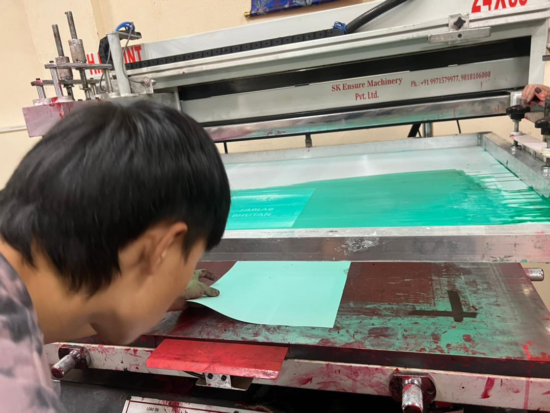
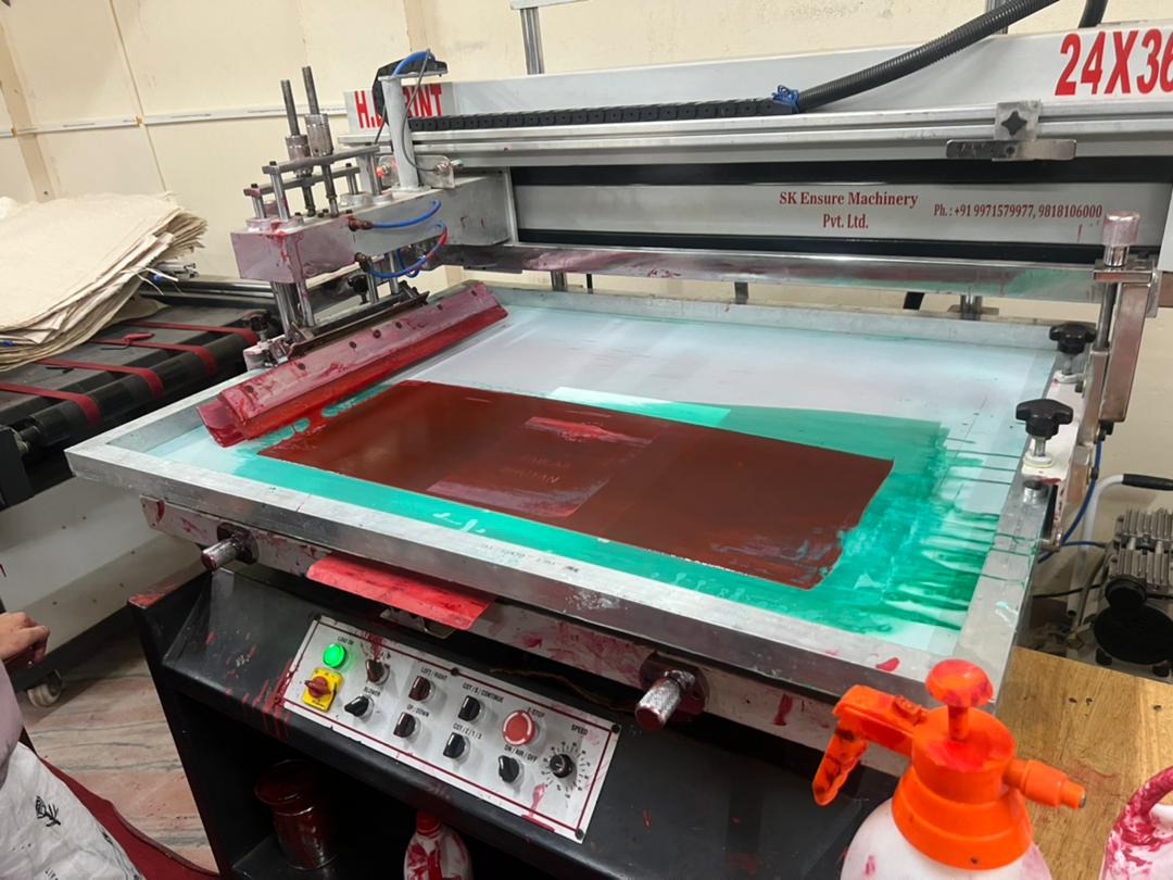
Since the equipment is pneumatically controlled, the pressure must be set at at least 6 bar. Once the pressure hits 6 bar, the pump is activated, and the printing process may begin. Printing merely takes the push of a button, which evenly distributes the ink, brings the machine to the floor with the paper, and spreads the ink once again.
- Oil paper must be used to print the pattern on the paper (We made use of computer paper which did not give consistent result)
- The print was not consistent since the room wasn't fully dark and the emulsion was exposed to low light.
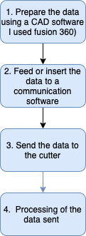
Following are the steps taken in using a printing Press
Final Result.
Below is an image of the final product. Due to some light exposure, the result wasn't as we expected it to be.
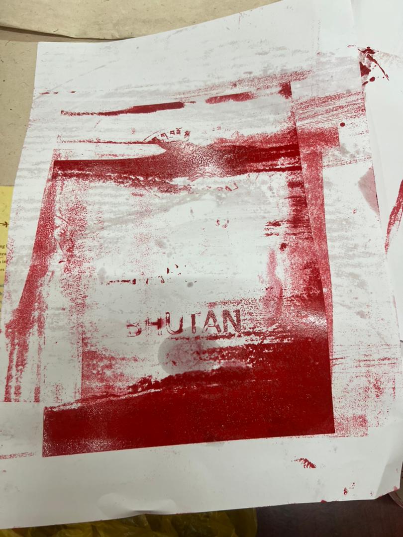
- We remove the document and look for contradictions. Our print's lack of uniformity was mostly caused by two factors.
Some Products from Screen printing.
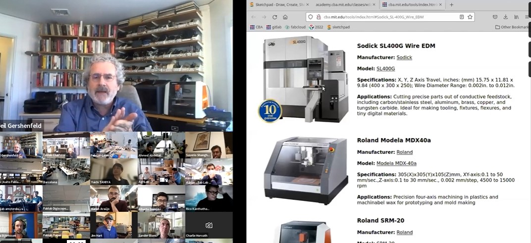
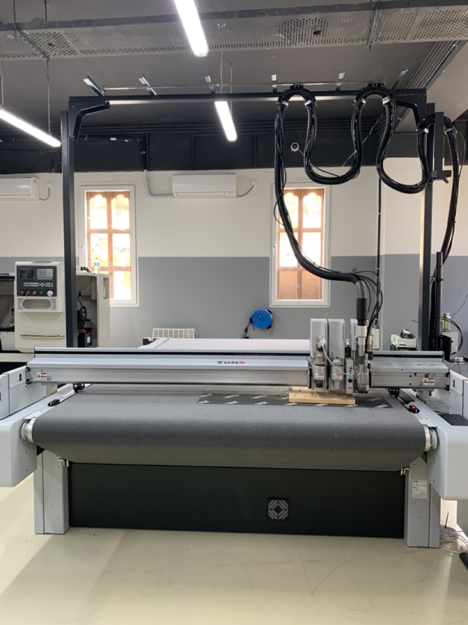
Zünd
I also worked with the Zünd G3 series. Since this is not available in our Fablab, I had to go to the super Fablab to carry out the assignment
Background on ZundWhat is Zund G3 Cutting System
The Zund G3 Digital Cutting System is among the most adaptable and customizable on the market. The Zund G3 flatbed digital cutting system is manufactured in Switzerland to the highest engineering requirements.
Modular ConceptG3 is modular in many respects, including construction, basic and optional equipment. It is also modular as an integrated element of your manufacturing department. G3 is capable of easily adjusting to changes in your cutting requirements. The advantages to you include knowing that your ROI is assured - both now and in the future.
The Zund G3 allows you to flexibly combine up to three tool modules. Module and tool changes are rapid and simple, reducing change-over times. The laser pointer or optional ICC camera aid in flawless registration in applications that require processing pre-printed images.
Wide Range of Tools and Options
The Zund G3 comes with a complete set of tools and attachments and can be adjusted to cut a broad variety of media and substances. There is a solution to your cutting needs, from ordinary cutting and creasing instruments to specialised V-Cut tools and oscillating cutters. The ultrasonic instrument that cuts and seals caters to vertical market applications such as emergency service livery creation.
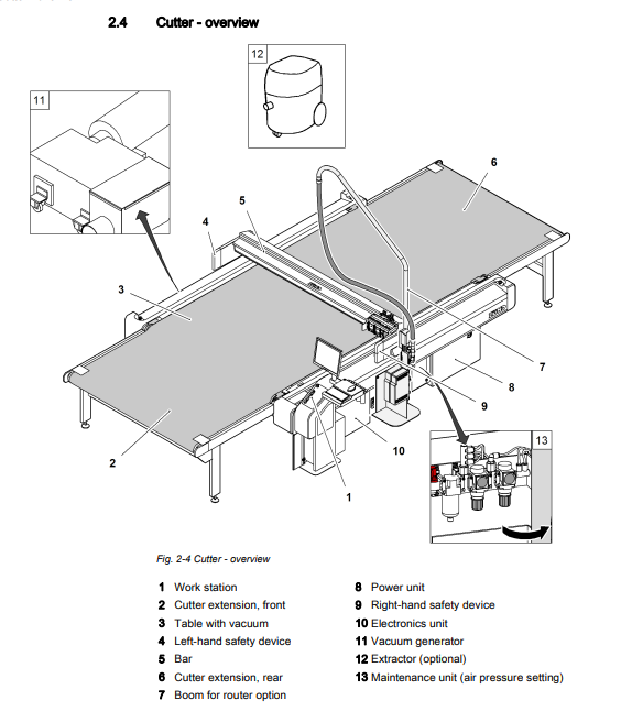
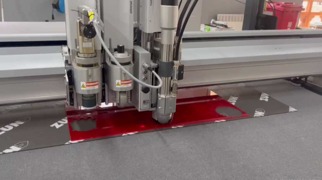
Overview of Zund Cutter
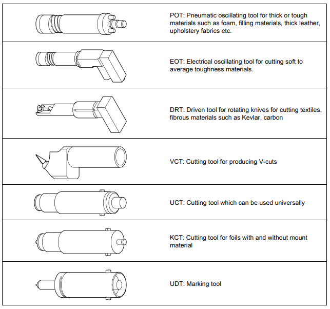
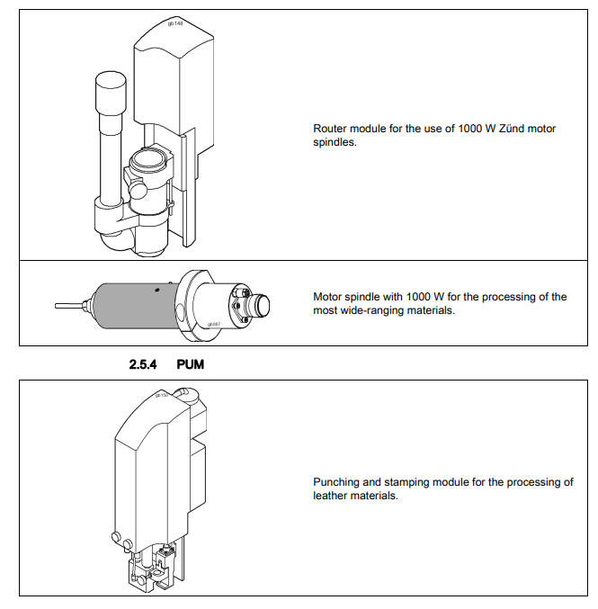
Tools Utilised by Zund
How the Zund Machine Works
Working Process
Designing in Fusion 360
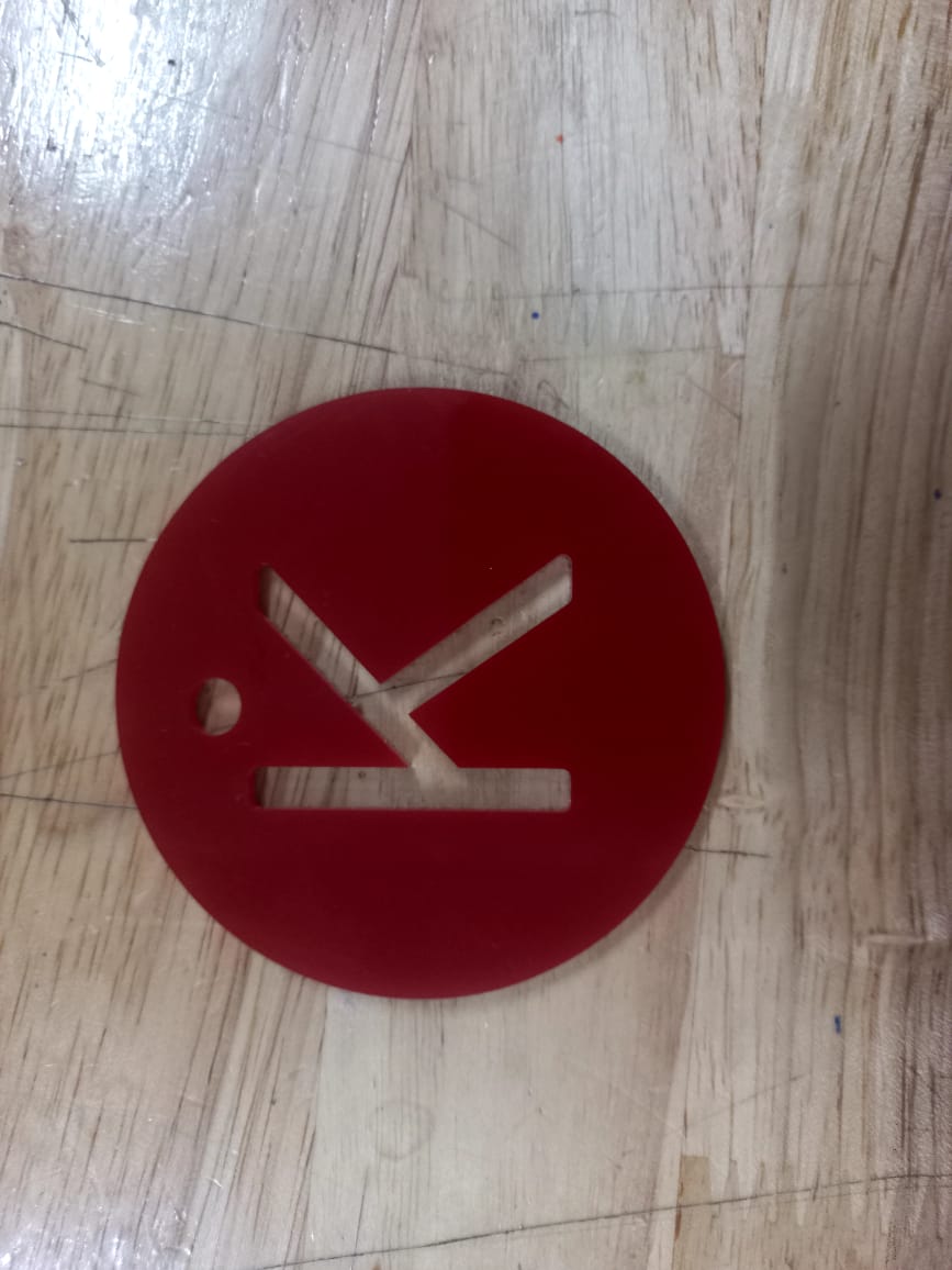
The following image shows the design that I decided to fabricate. It is a simple key tag with the initial K.
Design

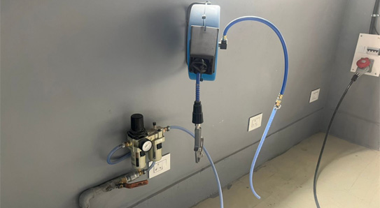
Applying Compressed Air
When using Zund, the first step is applying pressurized gas to a Zund machine. Air is used to keep the material on the machine bed in place which is also used in the Router Module.
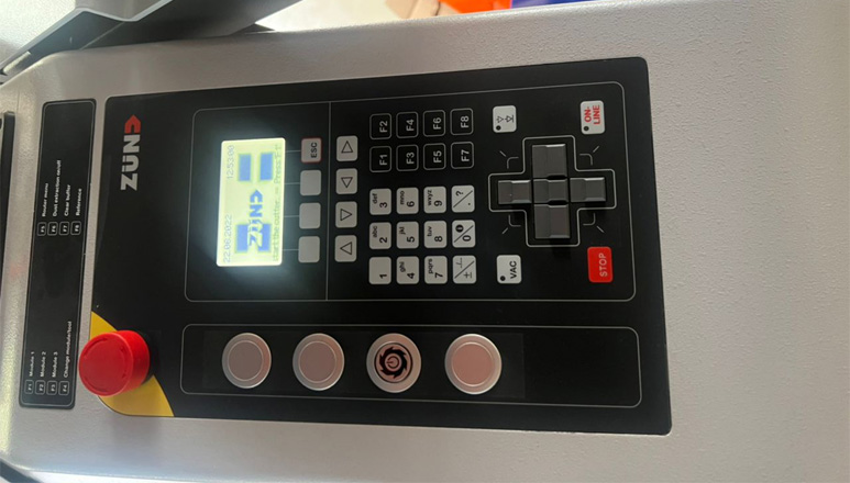
Tool Setting in Workstation
The next step is to configure the tool setting through the workstation. The workstation that has been talked about can be seen below:
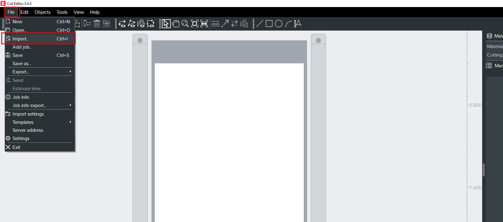
Sending the Design Data made in Fusion 360 of the Design Data to the Computer
Once the design process has been done, add the data to the communication program in either the dxf format or the svg format. The import process can be completed by clicking on the button import from file in the task bar.
And the softwares used for the Zund Cutter are Cuteditor and cutqueue softwares
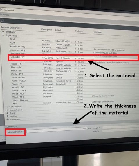
Once you have successfully transferred the design to the communication software, it is now time to choose the type of material from the top right panel. Zund g3 can use the following materials:
- Cardboard
- Corrugated cardboard
- Twin-wall sheets
- Wood
- Vinyl
- Plastics
- PA, PE, PUR, PS, PP, POM, PI, PVC
- Rubber
- Foam
- Textiles
- Leather
- Aluminum
- Fiber-reinforced plastics
- Glass
- Stone, Granite, Marble
- Acrylic
- Cork
- Plywood
- MDF
- Polyester
- Polycarbonate
- PET and PET-G
- Ceramics, Porcelain, Stoneware
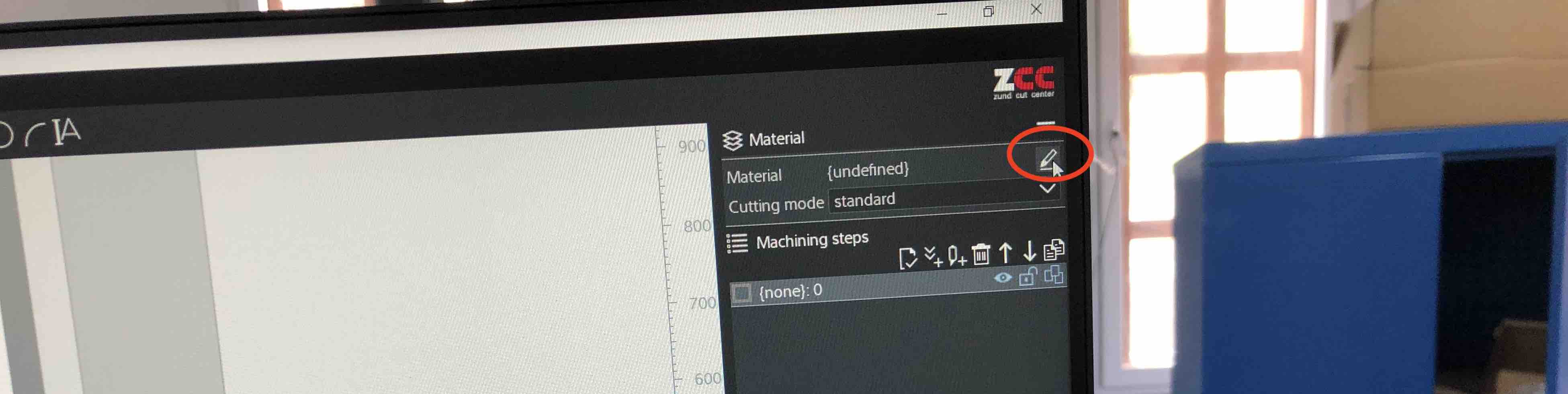
Once you have selected the material to be used. Now either through digital or non-digital means, measure the thickness of the material and then write it down. After that carry out the following process shown
Then choose the part that needs to be routed. This is carried out by right clicking the mouse and then providing a the title of your file.
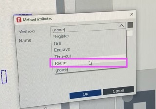
Then select the part you wanted to engrave by right clicking
As shown below, the following set of options are there to choose from. Dont be alarmed by the number of colorful options. The colorful options represent the different jobs available.
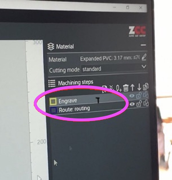
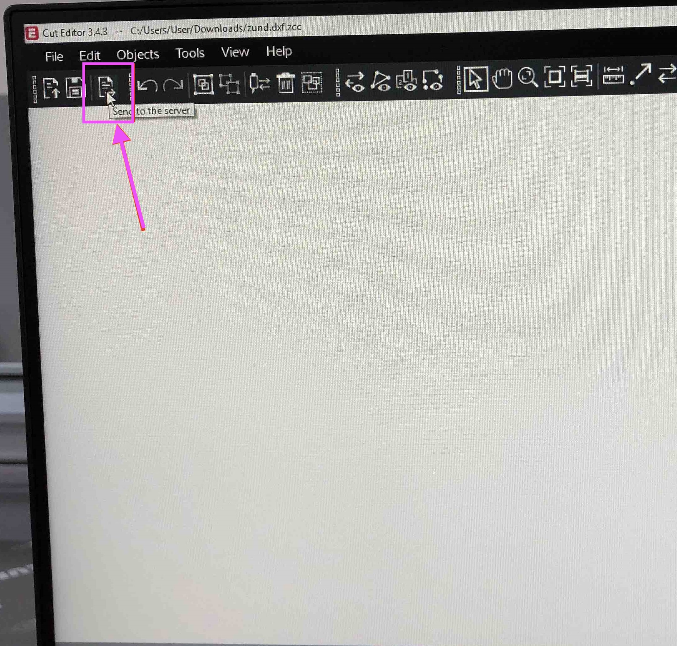
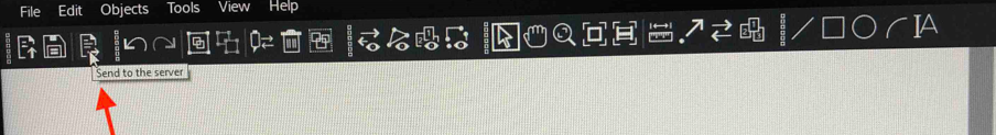
Once you have successsfully selected the jobs, click page icon. This is the send to server button
Working with Cut Queue
What is Cut QueueCut Queue facilitates production planning and order management. You can organize, sort, filter, or combine jobs for batch processing. Benefits at a glance. Scheduling and management of pending jobs. Sort and filter functions facilitate production planning.
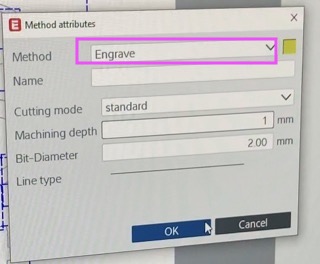
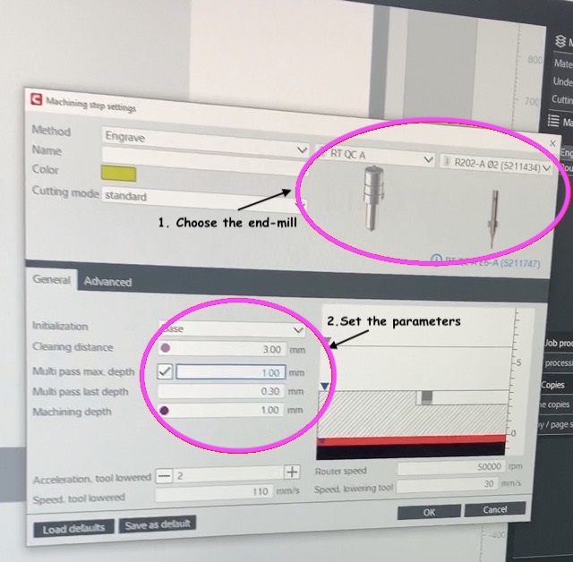
Open the cut queue, choose your task from the list, and then double-click on the engraving file. For the engrave approach, I used an end-mill= R202-A dia2 (5211434) with an engrave depth of 1mm and a 2mm toolbit. The other settings remained unchanged.
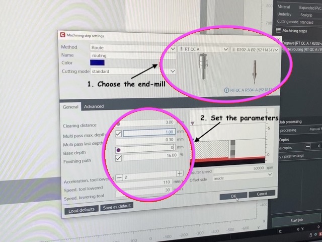
Settings for the routing method;
On the right side of your screen, click the routing file to access the machining step setting box. I used an end-mill with a diameter of R202-A dia2 (5211434), a multi-pass max depth of 1mm, and a base depth of 0mm.
Now turn on the vacuum before the job is made to run. Every end of the work place has controls for turning on/off the suction and restarting production. Once the material has been loaded, the vacuum on that end of the cutter can be reactivated. When the material is appropriately loaded, the operator presses the release button, allowing the operation to proceed.
Now select interactive mode. This allows you to manually shift the focus point.
Setting the XY Axis with the Arrow Symbol
This is the last step. Now it is time to start the fabrication by clicking on start cutting. Set the XY axis with the arrow symbol.
Then, using the laser point, mark a reference point. The reference point is represented by R on the screen, and you may set it by pressing Ctrl+R.
Begin the work once the reference point has been established.
Result